AIR CONDITIONERS
What is Standard on all Thermal Edge Air Conditioners?
STANDARD ON ALL THERMAL EDGE AIR CONDITIONING SYSTEMS
Thermal Edge Condensate Control is accomplished by routing refrigerant hot gas through our condensate boil off pan. The pan is located ahead of the condenser in the hottest point in the refrigerant system where the hot gas temperature is 180° F to 260° F.
Condensate is evaporated and the vapor is discharged by the condenser blower to the environment. Additionally, this condensate evaporation helps to pre-cool the hot gas, lowering the running amps and making our industrial air conditioner more efficient. By utilizing this pre-cool method, we lower the overall use of energy. This condensate boil off pan has enough water storage capacity to dehydrate the air in your equipment enclosure and vent it off without overflow so long as the enclosure doors are closed.
In the event that the enclosure will remain open, Thermal Edge does supply an Emergency Overflow Fitting on all of our units. Use of this Fitting is only for extreme open-door applications and should not be utilized in typical or even heavy applications.
- Condensate forms on evaporator and drips into a pan
- The drain forms a P-trap to maintain Closed Loop Performance
- Condensate collects in pan among loops of super-heated refrigerant to boil off normal build-up of condensate. Water vapor blown through condenser coil increases performance
Please Contact Thermal Edge for more information on use of this feature.
Air Conditioner Unit Specifications
What Are the Unit Specifications for CS011?
What Are the Unit Specifications for CS020?
What Are the Unit Specifications for HC101, HC121, and HC151?
What Are the Unit Specifications for HC20C?
What Are the Unit Specifications for NE010 and NE015?
What Are the Unit Specifications for NE020, NE030, and NE040?
What Are the Unit Specifications for NE050, NE060, and N080?
What is the Air Conditioner Product Overview?
Overview
Thank you for your purchase of the Thermal Edge Special Purpose Air Conditioner. Our air conditioning equipment is carefully designed to cool and dehumidify the air in electronic component enclosures. Thermal Edge has designed air conditioners for all types of electronic equipment enclosures providing capacity from 1,000 to 24,000 BTUH.
This manual will guide you through the installation, maintenance, diagnostics and advance operations of the CS011 Series Air Conditioners. This manual contains important information for the end-user who installs, maintains and/or operates the Air Conditioner.
Technical Support
By Phone: 972-580-0200 / 888-580-0202
(Monday – Friday, 7:30 am – 5:00 pm Central Time)
By Email: [email protected]
Our goal is to have continuous improvement for both our equipment and our documentation. We rely on and appreciate your feedback to help us achieve our goal. Our technical support team is glad to work with you if you require additional technical information not provided in this manual.
What is the Operation of TEI Air Conditioners?
Operation
Thermal Edge air conditioners will lower (or increase as necessary) the temperature inside an enclosure to ensure its proper operational temperature. Our air conditioners, when sized properly, will provide cooling or heating automatically controlled by the digital controller.
Thermal Edge air conditioners operate as a “closed loop” system with no exposure or introduction of outside air. This insures that the enclosure is separated from, and is not contaminated with, ambient air, dirt, chemicals, dust, moisture or foreign matter so that sensitive enclosure components are protected and are kept at your required operational temperature.
An air conditioner is designed to dehumidify and extract heat from an area, or provide heat to an area. The cooling is done using a simple refrigeration cycle. A product of this simple refrigeration cycle is excess humidity that condenses to a liquid.
Thermal Edge air conditioners are designed using an advanced refrigeration cycle and are equipped with a Condensate Removal System that changes the excess humidity liquid into a vapor which is then vented to the atmosphere. In the event of excess water vapor when the enclosure door has been left open there is an overflow hole on the bottom of every unit. Please contact Thermal Edge Inc. if you encounter excess water coming from your air conditioner.
What is the Air Conditioner Options - Sales Matrix
Title: Air Conditioner Option Sales Matrix
Department: Engineering
Objective: To provide a matrix of allowed air conditioner options and option combination.
Statement of Confidentiality
The Manual and other materials contain proprietary information, comprising Thermal Edge Inc.’s trade secrets. Please maintain the confidentiality of all proprietary information during and after the term of the use agreement. Also, please refrain from using this proprietary information in any other manner, including in any other business, without Thermal Edge Inc.’s written approval.
Thermal Edge Inc. reserves the right to revise and otherwise modify the Manual to reflect changes in the requirements, standards, and operating recommendations. The Manual is the sole property of Thermal Edge Inc. It must be returned upon the expiration or the termination of the term of use agreement.
By accepting the Manual you have read and understand the Statement of Confidentiality and will abide by its terms and conditions.
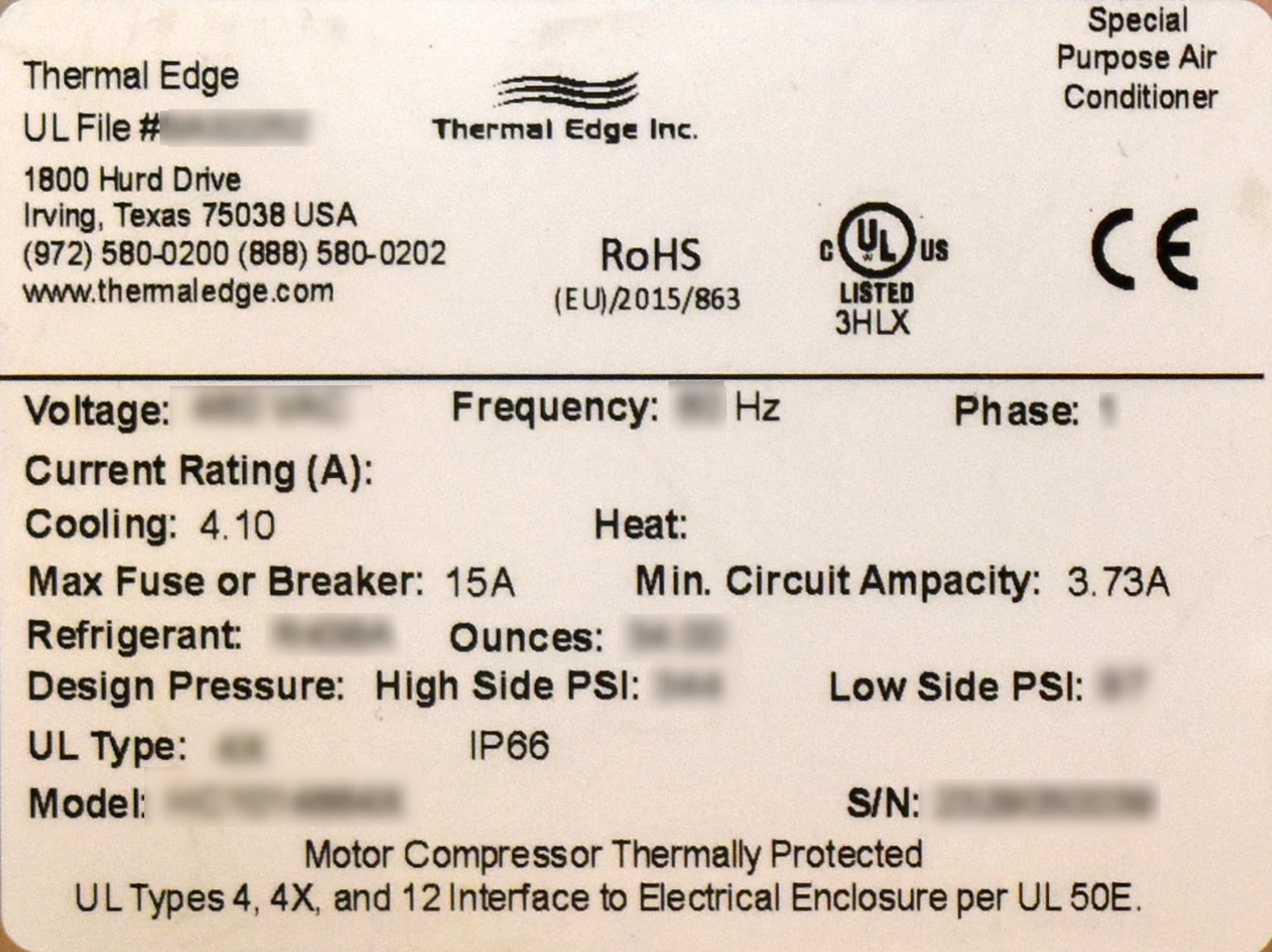
What Does the AC Unit Label look like?
Unit Label
Each air conditioner has a unit label, be sure to record the data from the label to the template below and keep this information in a safe place for warranty and ordering parts. To prevent damage to equipment, electrical panel and wiring, and to prevent personal injury, assure that the power source is compatible with the equipment before operating. When recharging, refrigeration type and amount must be the same as shown on the unit label or air conditioner will not operate properly or may be damaged and may result in the warranty voided and UL listing voided.
A2A HEAT EXCHANGERS
What are the options for Air to Air Heat Exchangers?
Options
The Thermal Edge A2A Compact, Slim, Deep, & Tall Series Heat Exchangers may be ordered with the following options. Review the list below for the specifications and functions of the option(s) that apply to your unit.
Corrosive Protection Package
We offer a corrosive protection package consisting of electro-coated (e-coat) coils for superior corrosion protection.
Custom Paint
Equipment may be ordered with any customer paint color.
Hazardous Location Unit
The Thermal Edge Hazardous Location units are in conformance with all requirements of UL and CUL for Class 1, Division 2, Groups A, B, C and D and will meet or exceed all the specifications for T6 areas.
What are the Unit Specifications for A2A Heat Exchangers?
Unit Specifications
The following table provides electrical specifications for the Thermal Edge A2A Compact, Slim, Deep, & Tall Series Heat Exchangers
A2AC – Compact Series
Standard Maximum Ambient: 160°F
Unit Weight: 20lbs
Mounting Dimensions (H x W x D): 16.5” x 11” x 3.5”
| Model |
Operating Voltage Range (Volts) |
Inrush Current
(Startup Current) (Amps) |
Loading Current
(Running Current) (Amps) |
SCCR
(Short Circuit Current Rating) (Amps) |
Rec. Circuit Protection Device Rating (Amps) |
VA Rating (Watts) |
Refrig. Type (amount in oz) |
Watt/ |
Free Air Flow (CFM) |
| A2AC040120 | 110-120 | 1.92 | 0.35 | *2 | 1.5 Amp* | 42 | CH3OH (0.41) |
11 | 131 |
| A2AC040230 | 220-240 | 1.65 | 0.18 | *2 | 1 Amp* | 42 | CH3OH (0.41) |
11 | 131 |
| A2AC040D24 | 21.6-26.4 | 3.90 | 0.80 | *2 | 2.5 Amp* | 20 | CH3OH (0.41) |
11 | 127 |
| A2AC040D48 | 43.2-52.8 | 2.00 | 0.40 | *2 | 1.25 Amp* | 20 | CH3OH (0.41) |
11 | 127 |
| A2AC080120 | 110-120 | 1.92 | 0.35 | *2 | 1.5 Amp* | 42 | CH3OH (0.41) |
22 | 131 |
| A2AC080230 | 220-240 | 1.65 | 0.18 | *2 | 1 Amp* | 42 | CH3OH (0.41) |
22 | 131 |
| A2AC080D24 | 21.6-26.4 | 3.90 | 0.80 | *2 | 2.5 Amp* | 20 | CH3OH (0.41) |
22 | 127 |
| A2AC080D48 | 43.2-52.8 | 2.00 | 0.40 | *2 | 1.25 Amp* | 20 | CH3OH (0.41) |
22 | 127 |
* Fast Acting Fuses with the following electrical characteristics are recommended. Do not use Extremely Fast Acting Fuse.
| % of Ampere Rating | Opening Time |
| 100 % | None |
| 135 % | 60min Maximum |
| 200 % | 120sec Maximum |
*2 SCCR rating is based on the SCCR rating for the circuit protection device installed in the panel / enclosure per UL50 & UL508a to protect the AC unit. Typically 10KA for Fast Acting Fuses.
A2AD – Deep Series
Standard Maximum Ambient: 160°F
Unit Weight: 24lbs
Mounting Dimensions (H x W x D): 16.5” x 11” x 5.5”
| Model |
Operating Voltage Range (Volts) |
Inrush Current
(Startup Current) (Amps) |
Loading Current
(Running Current) (Amps) |
SCCR
(Short Circuit Current Rating) (Amps) |
Rec. Circuit Protection Device Rating (Amps) |
VA Rating (Watts) |
Refrig. Type (amount in oz) |
Watt/ |
Free Air Flow (CFM) |
| A2AD120120 | 110-120 | 1.92 | 0.35 | *2 | 1.5 Amp* | 42 | CH3OH (0.81) |
33 | 131 |
| A2AD120230 | 220-240 | 1.65 | 0.18 | *2 | 1 Amp* | 42 | CH3OH (0.81) |
33 | 131 |
| A2AD120D24 | 21.6-26.4 | 3.90 | 0.80 | *2 | 2.5 Amp* | 20 | CH3OH (0.81) |
33 | 127 |
| A2AD120D48 | 43.2-52.8 | 2.00 | 0.40 | *2 | 1.25 Amp* | 20 | CH3OH (0.81) |
33 | 127 |
| A2AD160120 | 110-120 | 1.92 | 0.35 | *2 | 1.5 Amp* | 42 | CH3OH (0.81) |
44 | 131 |
| A2AD160230 | 220-240 | 1.65 | 0.18 | *2 | 1 Amp* | 42 | CH3OH (0.81) |
44 | 131 |
| A2AD160D24 | 21.6-26.4 | 3.90 | 0.80 | *2 | 2.5 Amp* | 20 | CH3OH (0.81) |
44 | 127 |
| A2AD160D48 | 43.2-52.8 | 2.00 | 0.40 | *2 | 1.25 Amp* | 20 | CH3OH (0.81) |
44 | 127 |
* Fast Acting Fuses with the following electrical characteristics are recommended. Do not use Extremely Fast Acting Fuse.
| % of Ampere Rating | Opening Time |
| 100 % | None |
| 135 % | 60min Maximum |
| 200 % | 120sec Maximum |
*2 SCCR rating is based on the SCCR rating for the circuit protection device installed in the panel / enclosure per UL50 & UL508a to protect the AC unit. Typically 10KA for Fast Acting Fuses.
A2AT – Tall Series
Standard Maximum Ambient: 160°F
Unit Weight: 36lbs
Mounting Dimensions (H x W x D): 29.0” x 13.88” x 5.5”
| Model |
Operating Voltage Range (Volts) |
Inrush Current
(Startup Current) (Amps) |
Loading Current
(Running Current) (Amps) |
SCCR
(Short Circuit Current Rating) (Amps) |
Rec. Circuit Protection Device Rating (Amps) |
VA Rating (Watts) |
Refrig. Type (amount in oz) |
Watt/ |
Free Air Flow (CFM) |
| A2AT200120 | 110-120 | 2.59 | 0.47 | *2 | 2 Amp* | 56 | CH3OH (1.22) |
55 | 211 |
| A2AT200230 | 220-240 | 1.32 | 0.24 | *2 | 1 Amp* | 56 | CH3OH (1.22) |
55 | 211 |
| A2AT200D24 | 21.6-26.4 | 9.7 | 1.94 | *2 | 6 Amp* | 47 | CH3OH (1.22) |
55 | 235 |
| A2AT200D48 | 43.2-52.8 | 4.8 | 0.96 | *2 | 3 Amp* | 47 | CH3OH (1.22) |
55 | 235 |
| A2AT260120 | 110-120 | 2.59 | 0.47 | *2 | 2 Amp* | 56 | CH3OH (1.22) |
72 | 211 |
| A2AT260230 | 220-240 | 1.32 | 0.24 | *2 | 1 Amp* | 56 | CH3OH (1.22) |
72 | 211 |
| A2AT260D24 | 21.6-26.4 | 9.7 | 1.94 | *2 | 6 Amp* | 47 | CH3OH (1.22) |
72 | 235 |
| A2AT260D48 | 43.2-52.8 | 4.8 | 0.96 | *2 | 3 Amp* | 47 | CH3OH (1.22) |
72 | 235 |
* Fast Acting Fuses with the following electrical characteristics are recommended. Do not use Extremely Fast Acting Fuse.
| % of Ampere Rating | Opening Time |
| 100 % | None |
| 135 % | 60min Maximum |
| 200 % | 120sec Maximum |
*2 SCCR rating is based on the SCCR rating for the circuit protection device installed in the panel / enclosure per UL50 & UL508a to protect the AC unit. Typically 10KA for Fast Acting Fuses.
What is the Preventative Maintenance For A2A Heat Exchangers?
Preventative Maintenance
Air to Air Heat Exchangers may require regular cleaning of the condenser air inlet section depending on the environmental conditions. Restriction to the flow of air over the condenser section will degrade the performance of the equipment, reduce cooling and can damage the fans.
Refer to Field Serviceable Parts section in this manual for details on parts that can be changed to help increase the uninterruptable life of the heat exchanger.
Condenser Air Inlet Cleaning
In the event of excess dust or particulates, clean the condenser air inlet section with a soft water spray or compressed air not to exceed 90 psi.
Condenser and Evaporator Fans
Thermal Edge Air to Air Heat Exchangers use high efficiency, long life, sealed ball bearing fans engineered for optimum performance that require no maintenance. Fans are removable and employ plug-in electrical connections.
What are the Field Serviceable Parts for A2A Heat Exchangers?
Field Serviceable Parts
Thermal Edge carefully designs and selects components with the maximum life expectancy. Due to OEM manufacturing tolerances, poor unit maintenance or extreme operating conditions, components may fail before their maximum life expectancy. The table below lists parts that are serviceable in the field by an Air Conditioner Technician.
| Part Description | Thermal Edge Part # |
| Unit Fans | Quantity 2 Per Unit |
| 120 VAC Compact, Slim & Deep Series | 41004-1-1 |
| 230 VAC Compact, Slim & Deep Series | 41004-2-1 |
| 24 VDC Compact, Slim & Deep Series | 41003-3-1 |
| 48 VDC Compact, Slim & Deep Series | 41003-5-1 |
| 120 VAC Tall Series | 41005-1-1 |
| 230 VAC Tall Series | 41005-2-1 |
| 24 VDC Tall Series | 41005-3-1 |
| 48 VDC Tall Series | 41010-4-1 |
Air to Air Troubleshooting Guide

FILTERED FANS
What are the Options For Filtered Fans
Options
The Thermal Edge Plastic & Metal Series Filter Fan Packages may be ordered with the following options. Review the list below for the specifications and functions of the option(s) that apply to your unit.
NEMA 3R Rain Shrouds
We offer a rain shroud that converts our filter fan packages to a NEMA 3R rating.
Custom Paint
Equipment may be ordered with any customer paint color.
Reverse Air Flow
Equipment may be ordered with reversed air flow configuration to operate as a depressurize system.
What are the Unit Specifications for Filtered Fans?
Unit Specifications
The following table provides electrical specifications for the Thermal Edge Plastic & Metal Series Filter Fan Packages.
Plastic & Metal Series
Standard Maximum Ambient: 158°F (70°C)
| Model |
Operating Voltage Range (Volts) |
Voltage Frequency (Hz) |
Inrush Current |
Loading Current |
SCCR |
Recommended Circuit Protection Device Rating (Amps)* |
Free Air Flow (CFM) |
Fan Speed (RPM) |
| PFFP-080-120 | 108–132 AC | 50/60 | 0.55 | 0.11 | *2 | 1.00 | 80 | 2900 |
| PFFP-080-230 | 207–253 AC | 50/60 | 0.30 | 0.06 | *2 | 0.75 | 80 | 2900 |
| PFFP-080-D24 | 21.6-26.4 DC | N/A | 0.75 | 0.19 | *2 | 1.00 | 80 | 2200 |
| P or MFFP-100-120 | 110–120 AC | 50/60 | 0.95 | 0.17/0.18 | *2 | 2.00 | 131 | 3300 |
| P or MFFP-100-230 | 220–240 AC | 50/60 | 0.60 | 0.10/0.11 | *2 | 1.00 | 131 | 3300 |
| P or MFFP-100-D24 | 21.6-26.4 DC | N/A | 0.90 | 0.23 | *2 | 1.25 | 100 | 3000 |
| P or MFFP-200-120 | 110–120 AC | 50/60 | 2.00 | 0.35/0.40 | *2 | 3.00 | 300 | 3300 |
| P or MFFP-200-230 | 220–240 AC | 50/60 | 1.15 | 0.20/0.22 | *2 | 2.00 | 300 | 3300 |
| P or MFFP-200-D24 | 21.6-26.4 DC | N/A | 8.4 | 2.1 | *2 | 10.00 | 300 | 3900 |
| PFFP-390-120 | 110–120 AC | 50/60 | 2.85 | 0.51/0.54 | *2 | 4.00 | 393 | 3300 ea |
| PFFP-390-230 | 220–240 AC | 50/60 | 1.80 | 0.30/0.33 | *2 | 3.00 | 39 | 3300 ea |
| PFFP-390-D24 | 21.6-26.4 DC | N/A | 2.70 | 0.69 | *2 | 3.00 | 300 | 3000 ea |
| P or MFFP-500-120 | 110–120 AC | 50/60 | 3.00 | 0.50/0.58 | *2 | 5.00 | 750 | 2200 |
| P or MFFP-500-230 | 220–240 AC | 50/60 | 1.50 | 0.25/0.30 | *2 | 3.00 | 750 | 2200 |
* Fast Acting Fuses with the following electrical characteristics are recommended. Do not use extremely Fast Acting Fuse.
| % of Ampere Rating | Opening Time |
| 100 % | None |
| 135% | 60min Maximum |
| 200% | 120sec Maximum |
*2 SCCR rating is based on the SCCR rating for the circuit protection device installed in the panel/enclosure per UL50 & UL508a to protect the AC unit. Typically 10KA for Fast Acting Fuses.
What is the Preventative Maintenance for Filtered Fans?
Preventative Maintenance
Filter fan packages may require regular filter replacement depending on the environmental conditions. Restriction to the flow of air will degrade the performance of the equipment, reduce cooling and can damage the fans. Restricted air flow due to neglecting a dirty filter may cause fan to overheat. Continuous operation in this condition will eventually damage the equipment and void the warranty.
Refer to Field Serviceable Parts section in this manual for details on parts that can be changed to help increase the uninterruptable life of the filter fan package.
Filter
Replace filters are readily available at Thermal Edge; a good preventative maintenance schedule is crucial to insure filter fan package optimal performance.
Fans
Thermal Edge Filter Fan Packages use high efficiency, long life, sealed ball bearing fans engineered for optimum performance that require no maintenance. Fans are removable and employ plug-in electrical connections
What are the Field Servicable Parts on Filtered Fans?
Field Serviceable Parts
Thermal Edge carefully designs and selects components with the maximum life expectancy. Due to OEM manufacturing tolerances, poor unit maintenance or extreme operating conditions, components may fail before their maximum life expectancy. The table below lists parts that are serviceable in the field by an Air Conditioner Technician.
| Part Description | Thermal Edge Part # |
| FFP-080 Series 12 Pack Filter | 44210 |
| FFP-100 Series 12 Pack Filter | 44211/44207 (Plastic/Metal) |
| FFP-200 Series 12 Pack Filter | 44212/44208 (Plastic/Metal) |
| FFP-390 Series 12 Pack Filter | 44213 |
| FFP-500 Series 12 Pack Filter | 44214/44209 (Plastic/Metal) |
| FFP-080 Fans | 120 VAC = 41006-1-1, 230 VAC = 41006-2-1, 24 VDC = 41006-3-1 |
| FFP-100 Fans | 120 VAC = 41004-1-1, 230 VAC = 41004-2-1, 24 VDC = 41003-3-1 |
| FFP-200 Fans | 120 VAC = 41025-1-1, 230 VAC = 41025-2-1, 24 VDC = 41010-3-1 |
| FFP-390 Fans | 120 VAC = 41004-1-1, 230 VAC = 41004-2-1, 24 VDC = 41003-3-1 |
| FFP – 500 Fans | 120 VAC = 41045-1-1, 230 VAC = 41045-2-1 |